Perfect for measuring the output of QRP oscillators
N5ESE RF Probe Construction
I’ve been building various oscillators recently and I needed a way to measure their RF output
Luckily, a nice circuit for this is available on the Net, and it includes background on the circuit, and a build article
N5ESE’s website has an RF Probe Circuit and build article – N5ese RF Probe Page
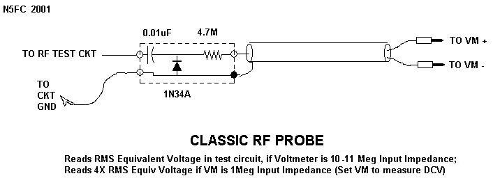
The circuit is basic and the probe’s read the RF AC Voltage, the circuit converts the AC RF to DC, and the multimeter displays the DC voltage, allowing for a conversion to Watts.
Although the circuit is simple, it is accurate, the limit of the circuit is the IN34A used to convert the RF to DC, any reading on the multimeter under 1/4 volt should be treated with caution, above 1/4 volt should be accurate
Perfect for measuring the output of QRP oscillators
RF Probe Circuit
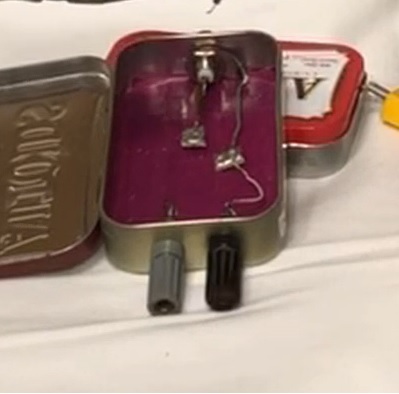
I decided to build the circuit in an Altoids Tin, with jacks for the probe and the multimeter connections
I chose the left side of the Tin for the probe connection, and mounted a BNC in the left end
I chose a probe cable to break out the BNC connector to 2 cables, 1 for the probe(center) and 1 for ground(shield)
A shorter cable is better, but a stock 1 ft cable works ok
So the right side was used for the multimeter connection
I chose to install banana jacks for the multimeter connection
This allowed me to use a cable with banana plugs on both ends to connect to the multimeter
I though this would allow more versatility on hookup, and less wire mess when not in use
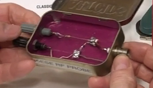
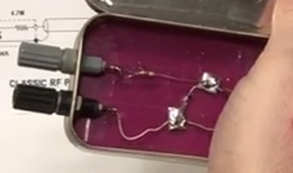
To simplify construction, I installed 2 small pads of circuit board to mount the components in the middle of the Altoids Tin
This allowed me to mount the 1N31 diode between the pads, and then connect each pad corresponding end points, greatly simplifying construction

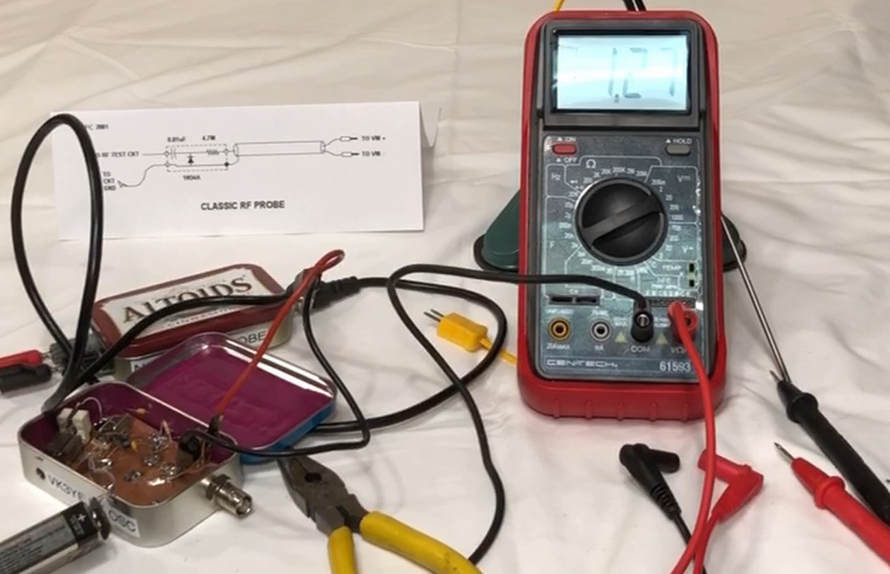
So how does it work?
Exactly as designed, attach the probe to a an oscillator and the DC equivalent voltage is displayed on the Multimeter

The Multimeter reading is then converted to Watts using this formula
Watts = (V_reading + 0.25)^2 / R_load
Example:
Voltage Reading = 1.31
(1.31+.25)*(1.31+.25)/50 = Watts
In Steps
(1.31+.25)=1.56
1.56*1.56 = 2.4336
2.5336 / 50 = .048672
Rounding = .05 Watts
or
50 Milliwatts
This turned out to be a great tool!
I can build two oscillators and measure the output to compare performance
I can also build small amplifiers and measure the output to check if the circuit matches the designed output power levels
Quick Video of the N5ESE RF Probe in Service
N5ESE RF Probe Construction
![]()