The process of building 3 QRP Dummy Loads
Building Low Power Dummy Loads for QRP Operating
I have been building a few QRP oscillators, experimenting with the different types and configurations
I need a few dummy loads to terminate the circuits when testing for frequency and power out, to simulate real world operating conditions
I decided to build three dummy loads, and use three different configurations
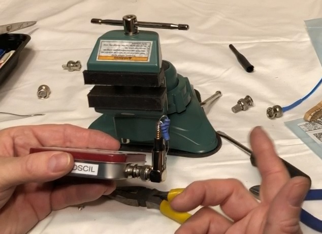
50 mw – an old arc-net 50 ohm terminator
1 watt – use 1 watt resisters on a BNC pigtail
2 watts – use 2 watt resistors on a BNC right angle connector salvaged from a wireless router
I ordered 1 watt and 2 watt resistors from Digi-key
I had the heat shrink tubing, arc-net terminator, the BNC pigtail and BNC right angle connector in my junk box
The only other items I needed were solder and a soldering iron
The arc-net Terminator was ready to go, but was only good for extremely low power oscillators, but useful when building the first stage of oscillators
So I started assembling the parts for the 1 Watt and 2 Watt Dummy Loads
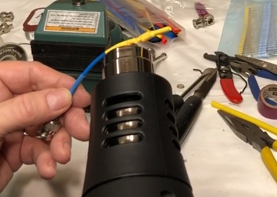
The BNC pig tail needs resistors soldered between the center wire and the shield
The bare wires could provide an RF burn if touched, so they need covered, and heat shrink tubing work well and look better than tape
The BNC right angle connection needs resistors soldered between the center spring and the base of the connection
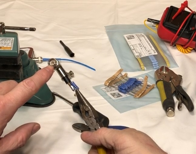
The spring was easy to solder, but soldering to the connection base required a lot heat to get a good solder joint
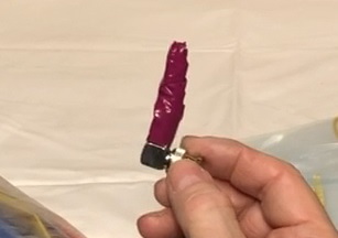
The completed dummy load installed on a oscillator built in an Altoids Tin
The 2 watt resistors were a little large and I did not have a large enough piece of heat shrink tube, so I used electrical tape instead
This project’s total time to complete was about 15 minutes, and I now have three different dummy loads to use while building small oscillators and low power radios
Watch the Dummy Load Build Video
Building Low Power Dummy Loads for QRP Operating
![]()