uBitx v5 Adding a Fuse and New Power Switch
The kit provides a DC panel mount jack, there are three pins, but only 2 are used – Ground and Power
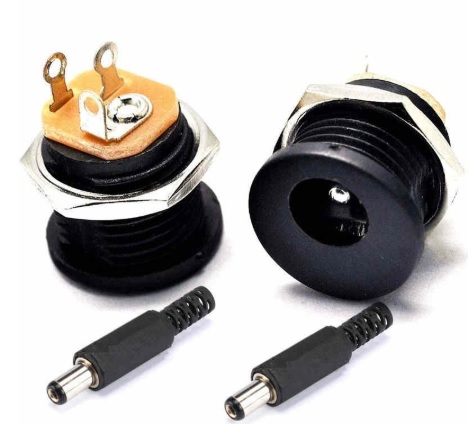
The Kit provides a DC Power Connector to be wired to a 12v supply, but I already have a 5 amp power supply with the correct connector, so I did not need the supplied power connect, and most hams are likely to have a Wall Wart that will work with the ubitx v5
The kit also provides a 1N4007 to stop reverse polarity from damaging your system
Following the direction assumes you are NOT using a separate power supply for the PA – if you are using a separate power supply for the PA, wire up two DC power jacks, one for the PA and one for everything else
To use one Power Supply for both PA and the System, connect both the Brown and Red Wires together
Depending where you look, the kit requires either a 2A or 3A 12v supply for the system, and will support a higher voltage for the PA
I wired my uBitx for a 12v 5A supply for both PA and the System, using one power supply, I can separate them out later if needed
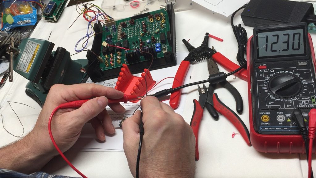
Time to Test
Ensure the power interface cable is not connected to the ubitx main board before testing
Connect the power supply to the 2.1mm Power Jack, and test the solder connections to ensure vcc and ground are correct, and the power does not exceed 12 volts (12.5 is ok)
The manual does not recommend turning on the ubitx until all the connections are completed, The uBitx might go into spontaneous Transmit without the key jack wired
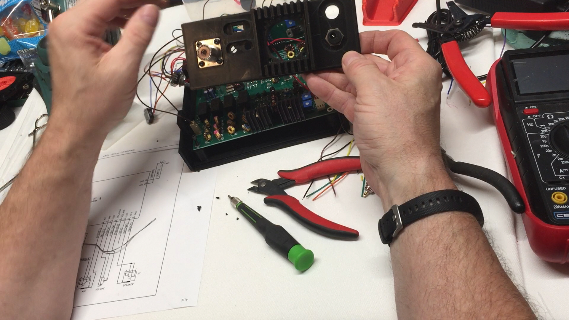
Video of the Power Jack Wireup
uBitx v5 Adding a Fuse and New Power Switch
![]()